Seeq Module TM-EM2H Ethernet Transceiver Is and 18 similar items

SEEQ MODULE TM-EM2H Ethernet Transceiver ISOlation Transformer DC/DC NEW $9
$8.91
(It may be possible to pay only $7.75 instead of $8.91 when you
use your bCredits at checkout)
Sign up and get $5.00 bCredits free to use at checkout and another $5.00 bCredits when you make your first purchase. More info
Share & earn! Sign in, share this or any listing, and you’ll get commission when it sells.
Learn more
View full item details »

Shipping options
Offer policy
OBO - Seller accepts offers on this item.
Details
Return policy
Full refund available for DOAs
Purchase protection
Catalog info
Payment options
PayPal accepted
PayPal Credit accepted
Venmo accepted
PayPal, MasterCard, Visa, Discover, and American Express accepted
Maestro accepted
Amazon Pay accepted
Nuvei accepted
View full item details »
Shipping options
Offer policy
OBO - Seller accepts offers on this item.
Details
Return policy
Full refund available for DOAs
Purchase protection
Catalog info
Payment options
PayPal accepted
PayPal Credit accepted
Venmo accepted
PayPal, MasterCard, Visa, Discover, and American Express accepted
Maestro accepted
Amazon Pay accepted
Nuvei accepted
Item traits
| Category: | |
|---|---|
| Quantity Available: |
36 in stock |
| Condition: |
New |
| MPN: |
TM-EM2H |
| UPC: |
Does not apply |
| Brand: |
Seeq |
Listing details
| Shipping discount: |
Shipping weights of all items added together for savings. |
|---|---|
| Posted for sale: |
More than a week ago |
| Item number: |
456441398 |
Item description
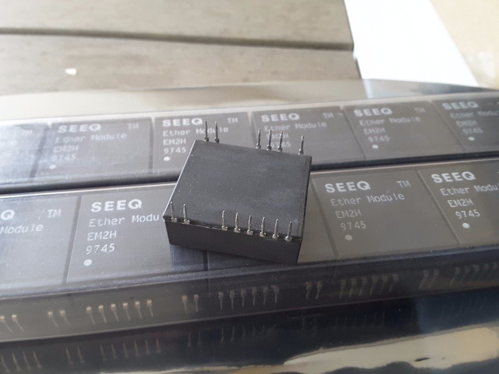
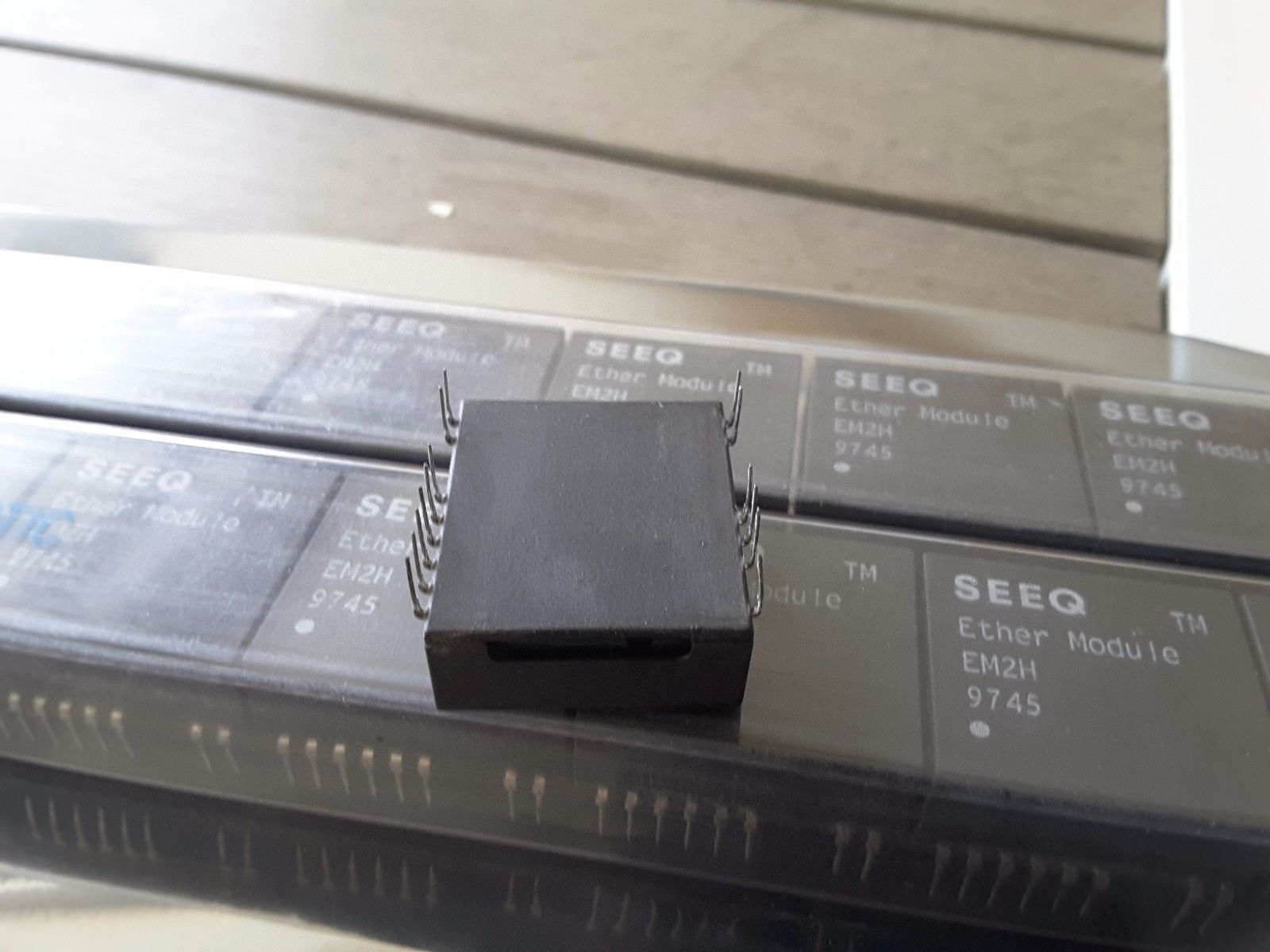
SEEQ ETHER MODULE TM-EM2H Ethernet Transceiver ISOlation Transformer DC/DC $19
SALE $9 EACH BO
NEW OLD STOCK. TIN LEADS ARE TARNISHED FROM AGE.
STILL GUARANTEED.
PLEASE MAKE SURE THESE SPECS APPLY TO THIS DEVICE.. OBTAINED ON THE INTERNET.
Ethernet Transceiver Module with on Board Isolation Transformer DC/DC Converter
97176 Note: Check for latest Data Sheet revision before starting any designs. SEEQ Data Sheets are now on the Web, at www.lsilogic.com. This document is an LSI Logic document. Any reference to SEEQ Technology should be considered LSI Logic.
s Collision Test Generator, externally deselectable to work with any ANSI/IEEE 802.3 and ISO 8802-3 repeater. s Detects and reports network collisions in both transmit and receive modes. s Implemented with SEEQ proprietary high voltage (20V) and high performance CMOS process. s Loopback test detects network cable opens or shorts. s Power On Reset prevents transmission during power up. s Regulated to DC Converter on board. s Disable pin to power-down module. s Isolation Transformer on board. s Optimized for Hub and Repeater Applications. EM2H is Available for Adapter Card Applications
The Thin Net (Cheapernet) module provides a complete Local Area Network interface for a station, without a transceiver cable. The is an encased module containing all circuit components for a complete Thin Net COAX interface and includes an on-board SEEQ CMOS 83C92C transceiver DC/DC converter and isolation transformer. The module is compatible with ANSI/IEEE 802.3 and ISO 8802-3. The module is part of a chipset manufactured by SEEQ Technology to provide the basic components for a LAN interface board. The other components include the 80C03, 8005/80C04A Advanced Ethernet Data Link Controllers (AEDLC TM), the or 8023A Manchester Code Converter (MCC TM), and the 80C24 Media Interface adapter (MIA).
Features
s The module is compatible with ANSI/IEEE 802.3 and ISO 8802-3 Standards for Thin Net (10BASE2). s Contains all Thin Net COAX transceiver functions within a single encased unit. s Squelch circuits on all signal inputs to eliminate noise.
LINE DRIVER 1.0 K VEE 1.0 K VEE _ 18 LOW PASS FILTER + COLLISION TEST GENERATOR 10 MHz OSILLATOR JABBER TIMER COLLISION COMPARATOR + VEE RX SQUELCH COAX CABLE
2 LINE DRIVER TX SQUELCH V EE REGULATED DC/DC CONV GND 1.0 K
Figure 1. Ethernet Transceiver Module Block Diagram
AEDLC, MCC and Ether Module are trademarks of SEEQ Technology, Inc.
Description
The Thin Net module connects the station equipment to a Thin Net (Cheapernet) COAX cable. The on-board 83C92C CMOS COAX transceiver provides the drive current and wave shaping for the transmit signals. It supplies receive signal equalization, collision detection and squelch. 5-6 TX Transmit Data Input. A balanced line receiver input to the module from the MCC for transmit packets. HBE Heartbeat Enable. This input enables the Collision (also called Heartbeat) Test when connected to ground, and disables the test when connected to VEE. SYS GND Ground. System Ground is referenced to VCC. RXI Network Signal Receiver. Connects to the network COAX center conductor, and receives packet data and detects the collision voltage level. TXO Network Signal Transmitter. Connects to the network COAX center conductor through an internal 1N916 diode, and transmits all signals from the MCC to the network. CDS Collision Detect Sense. Connects directly to the network shield, and references the collision detection voltage level.
PIN # FUNCTION 1-2 CD Collision Output. A balanced 10 MHz differential output to the station equipment when a collision is detected, when excessive data transmission occurs (jabber), or during the Collision Test (Heartbeat Test). 4 11 RX Receive Data Output. Line Driver output to the MCC Receive inputs. VEE Negative Supply. Nominally 9 volts referenced to COAX shield ground. An on-board DC-DC power converter provides 9 volt power for the on-board module , and DC isolation from the station equipment to prevent ground loop current.
12 DM Disable module is an active low signal (internal 10K pullup) that may be utilized to turn off the Ether module in the event an alternative transceiver is used, or for power conservation purposes. The TXO signal is disabled when not transmitting to prevent noise on the network. If the COAX cable is shorted or open, no transmitted data appears on the Receiver input. This condition can be detected by the station equipment by running a loopback test. Collision Detection The Collision detector monitors the COAX Center Conductor and senses the voltage conditions created by a collision, where the COAX shield is used as a reference. A collision condition can be detected when two or more stations are transmitting, whether or not the local Transmitter is activated. This is called Receive Mode Collision Detection. The detector signals a collision by sending the 10 MHz oscillator signal through the Collision Pair (CD) to the MCC. The HeartbeatTest is performed at the end of each transmitted data packet to verify the operation of the detector. A collision causes a 2.0 volt average DC level on the center conductor of the network cable. This level passes through a 4-pole Bessel low-pass filter for averaging. The resulting signal is measured by a voltage comparator against the threshold voltage VCD of about -1.5 volts. A collision is indicated when the center conductor average level is more negative than the CDS level by the threshold VCD. The line driver is enabled within ns of the onset of the collision, and the 10 MHz signal is sent to the station equipment. The Heartbeat Test is a short burst of the collision signal generated immediately after the transmission of a packet. This test enables the 10 MHz collision signal for about 1
The module has five main functions, as shown in the block diagram. These are the Transmitter; the Collision Detector; the Jabber Timer; the Receiver; and the DC/DC Converter. The on-board SEEQ 83C92C provides all functions except DC/DC conversion and AUI signal isolation. The Transmitter The Transmitter takes differential output signals from the MCC, and outputs these signals at the correct levels to the network. The transmit signal is sent to the module via a balanced differential pair (TX). A squelch circuit prevents the Transmitter Output from responding to noise on the TX pair. The Transmitter has an open-collector current driver output using the VEE supply. Rise and fall times are controlled and set at 25 ns/V to lessen the higher harmonics. Drive current levels are set by a bandgap voltage reference and a internal 1K resistor. An internal diode is also added to reduce COAX loading and capacitance to comply with the ISO and ANSI/IEEE specifications. The transmit squelch circuit blocks signals with pulse widths less than 15 nanoseconds, (negative-going), or with levels of less than 175 millivolts. The squelch circuits turn the Transmitter off at the end of a packet if the signal stays higher than 175 millivolts for more than 190 nanoseconds. See Figure 3, the Transmitter Timing Diagram.
The sale of this item may be subject to regulation by the U.S. Food and Drug Administration and state and local regulatory agencies. If so, do not bid on this item unless you are an authorized purchaser. If the item is subject to FDA regulation, I will verify your status as an authorized purchaser of this item before shipping
|
Why are we showing these items?
Booth
yaba1957's booth |

|

 MU9C4320L-90TDC 4K X 32 CONTENT ADDRESSABLE MEMORY (CAM) $59 - $58.41")

 AD AD8044AN ANALOG DEVICES NEW NOW (LOT OF 6 PCS) SALE $49 - $47.76")
 Ads7843E Texas Instruments Touch Scr NEW (LOT OF 50 PCS) SALE $49 - $38.00")

 CR BOX SUPER RARE NE... - $58.41")


 KA7808 SAMSUNG 8V FIXED POSITIVE REGULATOR PSFM3 NOS NEW LOT OF 50... - $24.36")
 XR2567CP Dual Tone Decoder 0.01 Hz to 500 kHz NEW IN FACTORY TUBE R... - $76.98")

 LXT305APE FRAMER E1/T1 5V 28-PIN PLCC NEW NEW $9.99 - $9.74")
-
Refine your browsing experience
We can show you more items that are exactly like the original item, or we can show you items that are similar in spirit. By default we show you a mix.
 DS1231-35 DALLAS MAXIM INTEGRATED PRODUCTS DS123135 NEW SALE $19 - $18.51")

 LINEAR TECH LTC1198-2BCS8 Voltage Regulator New NOS SALE USA $9.99 - $9.74")
 LT1781CS RARE LTC Dual Transmitter/Receiver RS-232 16-Pin SOIC N... - $98.01")
 MIC39101-2.5BM MICREL 1 AMP Low Voltage Low-Dropout Regulator ... - $8.91")
This item has been added to your cart
 SEEQ MODULE TM-EM2H Ethernet Transceiver ISOlation Transformer DC/DC NEW $9 added to cart.
36 available in stock
SEEQ MODULE TM-EM2H Ethernet Transceiver ISOlation Transformer DC/DC NEW $9 added to cart.
36 available in stock
View Cart or continue shopping.
 Please wait while we finish adding this item to your cart.
Get an item reminder
We'll email you a link to your item now and follow up with a single reminder (if you'd like one). That's it! No spam, no hassle.
Already have an account?
Log in and add this item to your wish list.